ToF: Non-line-of-sight (NLOS) imaging turns the corner to usability
FIGURE 1. Non-line-of-sight (NLOS) imaging relies on precisely measuring the time of flight of ultrashort light pulses from a laser source to a high-speed detector such as a single-photon avalanche detector (SPAD). The red solid line shows the path of an ultrashort pulse passing through a window to a matte “relay wall” that diffusely reflects light into a room, where it illuminates targets. The dashed blue line shows diffuse reflection back to the relay wall from a desk and table in the front of the room, and from a “bad guy” hiding in the background, who is illuminated indirectly. The green dashed line shows how the relay wall then diffusely reflects some of that light back through the window to the detector. The detector times the arrival of the few photons that return and calculates their path to map the interior of the room and spot the lurking “bad guy.”
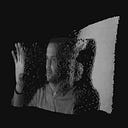
FIGURE 2. Return from the setup shown in Figure 1. Timing starts at the start of the laser pulse, but the detector ignores early photons reflected from the relay wall. The first returns recorded are from light that bounces back from the desk and table in the front of the room. Weaker signals are returned later after multiple bounces from the “bad guy” in the back of the room.
FIGURE 3. The test scene (a) compared with signals calculated from returns (b); the data is built up over many pulses.(Courtesy of Andreas Velten)
The quest for optics to see around corners is an old one. Polish astronomer Johannes Hevelius made a primitive periscope in 1647, but not until 1854 did French inventor Hippolyte Marié-Davy invent a naval version. Trying to view an out-of-sight instrument dial in 1926 led RCA radio engineer Clarence W. Hansell to invent the flexible fiber-optic bundle for imaging. What’s now called non-line-of-sight (NLOS) imaging has become a hot topic in photonics, and shows up on the wish lists of military planners trying to defend against insurgents lurking in old buildings waiting to attack troops.
The modern quest is not to invent a new type of periscope, but to peer around corners into hidden areas not directly viewable with mirrors or other conventional optics that see only objects in the line of sight. The hot new approach that revived the quest is directing very short pulses of light at a “relay wall” visible from outside so the light is scattered through the hidden area and illuminates objects out of direct sight. Those hidden objects then scatter some light back to the relay wall, where it can be observed from outside. Using ultrashort pulses and detectors makes it possible to measure the time of flight of the scattered light, and those observations could yield enough information to map what is in the hidden area.
How it works
Like a lidar, the NLOS system starts by firing a short pulse of light, but the light is directed at a point on the relay wall which will scatter the light into the hidden zone. Triggering the pulse also triggers a detection system that watches another point on the wall for light scattered from the hidden area. Objects in the hidden zone then scatter the light from the relay wall; some of the scattered light goes directly to the wall, but other light scatters to other hidden objects, which scatter some light back to the wall. As in lidar, only a very small fraction of the photons in the original pulse wind up in the return signal sensed by the detector, which records their time of flight from the start of the pulse.
An imaging processor collects the return signals, their location on the wall, and their time of flight through the hidden area. Then, the processing system algorithms reconstruct the path of the light inside the hidden area, including where the light encountered objects that scattered it back to the relay wall. The processing system collects data returned from a series of pulses scattered by the relay wall into the hidden area to build up a digital 3D map of the collection of objects in the room. Think of the whole imaging system as a virtual camera that reconstructs the scene computationally; Figure 1 shows how the system works.
Ramesh Raskar’s Camera Culture group at the MIT Media Lab (Cambridge, MA) developed and published the concept in 2010.1 Andreas Velten, then at MIT and now a professor at the University of Wisconsin (Madison, WI), went on to demonstrate the concept. In 2012, he and colleagues reported using a streak camera to record the returned signal and process the signal streak-camera images to record a three-dimensional image of a small mannequin inside the hidden volume.2 The scattering process caused most of spatial information in the light to be lost, but capturing the ultrafast information on the time of flight allowed them to compensate for the loss.
Their demonstration was impressive, yet it was limited to collecting photons that had made only three scattering bounces: from the relay wall to the surface of the object facing the wall, from the object back to the wall, and from the wall to the streak camera. That could show only the three-dimensional side of the mannequin facing the relay wall. Some light scattered from the wall then was scattered off the mannequin or other objects in the hidden area, but the scattering process was so inefficient that few photons remained after their additional bounces off the other objects and their signal was too weak to detect. At the time, Velten expressed hope that better lasers and sensors and more powerful algorithms could recover enough information on reflectance, refraction, and scattering to allow reconstruction of hidden objects in the scene.
Velten’s report got wide attention at the time because it demonstrated an optical feat long regarded as extraordinary. However, like invisibility cloaking with metamaterials, it was an elegant demonstration of a headline-grabbing topic, but was far from real-world applications. Nonetheless, it was enough to stimulate more research, including a DARPA program called REVEAL, for Revolutionary Enhancement of Visibility by Exploiting Active Light fields, that was launched in 2015.3
A need for new technology
The DARPA program recognized a need for new technology to overcome the limitations of the initial demonstrations. In a review paper published in June 2020, Daniele Faccio of the University of Glasgow (Glasgow, Scotland), Velten, and Gordon Wetzstein of Stanford University (Stanford, CA) describe three developments needed for practical use.4 Perhaps the most obvious need was to fill in the picture behind the front layer of the scene that scattered the most light back to the relay wall. More scattering events could distribute light deeper into more hidden parts of the scene, but the strength of the return signal drops rapidly with the number of scatterings (see Fig. 2). Detecting such faint signals as well as brighter ones requires single-photon detectors that can be gated or have a high dynamic range.
FIGURE 2. Return from the setup shown in Figure 1. Timing starts at the start of the laser pulse, but the detector ignores early photons reflected from the relay wall. The first returns recorded are from light that bounces back from the desk and table in the front of the room. Weaker signals are returned later after multiple bounces from the “bad guy” in the back of the room.
A second challenge is that deducing the location and three-dimensional configuration of a hidden object from intensity measurements is an “ill-posed” problem, one that lacks a single unique solution or has solutions that vary discontinuously as a function of input data. In this case, the key problem is inadequate sampling. A robust NLOS system could overcome that limitation, but would need to measure time with picosecond accuracy to have prior information on the imaged objects, or would have to offer an unconventional solution.
A final challenge is developing algorithms that can quickly and efficiently work backward from the image data collected by the sensor to calculate the full three-dimensional shape of a hidden object using only the memory of a single computer.
The paper reviews a number of recent studies and concludes that the most promising approach for NLOS imaging is time-resolved systems that combine ultrashort-pulse light sources with single-photon detectors. The preferred light sources are ultrashort laser pulses focused onto a relay wall so the light scatters into the hidden area. Light travels about 3 cm in 100 ps, so pulse durations must be no longer to get reasonable spatial and temporal resolution. Pulses of 100 fs would freeze time into shorter 30 μm slices in space. The laser beam scans the relay wall so scattered light from pulses radiates from points across the relay wall to illuminate the hidden area. Some scattered light bounces from other walls or parts of hidden objects to other points in the hidden area, so the light may take multiple bounces before a few photons from the original scattered pulse return to the relay wall, where they can be recorded by a detector or camera. Figure 3 compares the actual scene with the image calculated from the time of flight returns.
FIGURE 3. The test scene (a) compared with signals calculated from returns (b); the data is built up over many pulses.(Courtesy of Andreas Velten)
Sensitive high-speed detectors or cameras also are essential for high resolution in time and space. Single-photon avalanche diodes (SPADs) have been used for many NLOS imaging experiments.5 SPADs are avalanche photodiodes operated at a high bias voltage, so detection of a single photon produces an avalanche of carriers and a high signal in Geiger mode. The detection system counts the time from emission of the laser pulse to the SPAD’s detection of a single-photon return, and photon arrivals are recorded on a histogram for analysis. For precise measurements, the detector is shut off for tens or hundreds of nanoseconds after detection of a photon, giving time to record multibounce returns. SPADs can detect up to 40% of incident photons.
Commercially, SPADs are available as single-element and array detectors, both of which can be used in NLOS imaging. Currently, most SPAD arrays are developed for lidar, and those designs need modification for best performance in NLOS imaging. Needed improvements include better time resolution, higher fill factors, gating out direct light, and more flexibility in photon time scales.